-
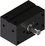
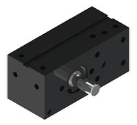
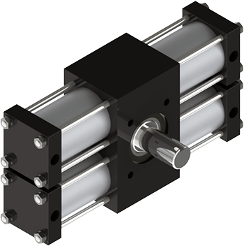
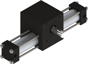
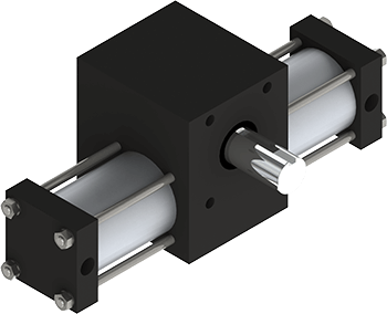
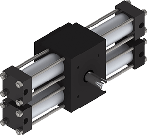
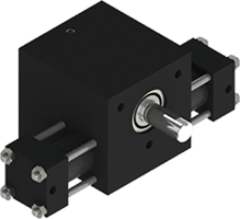
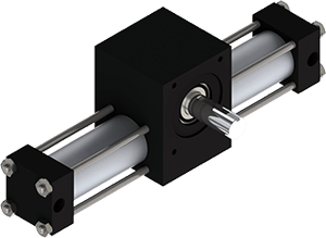
 Rotary Rotary ActuatorsCompactA032*80psi
 Torque: 9 in-lb*
Shaft: 1/4" or 3/8"
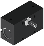
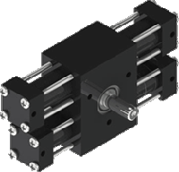
DiameterAL75*80psi Torque: 7-14 in-lb*
Shaft: 1/4"
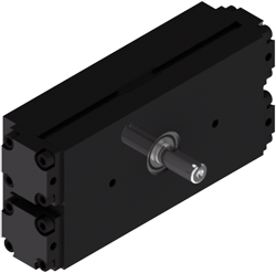
DiameterA752*80psi Torque: 35 in-lb*
Shaft: 3/8"
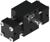
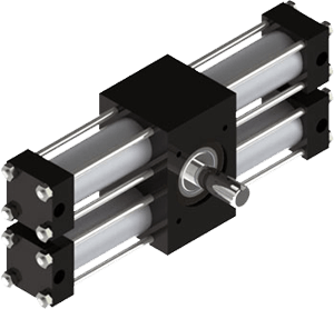
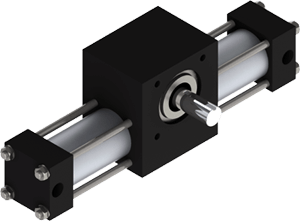
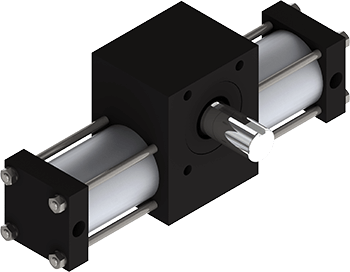
DiameterSingle Rack Tie-RodA01*80psi Torque: 6 in-lb*
Shaft: 3/16" or 1/4"
DiameterA1*80psi Torque: 12 in-lb*
Shaft: 1/4" or 3/8"
DiameterA2*80psi Torque: 39 in-lb*
Shaft: 1/2"
DiameterA3*80psi Torque: 119 in-lb*
Shaft: 3/4"
DiameterA4*80psi Torque: 277 in-lb*
Shaft: 1" or 1 1/8"
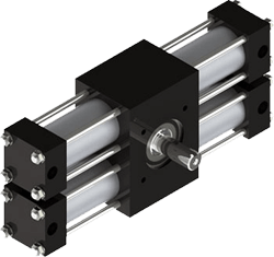
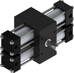
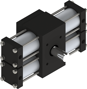
DiameterDual Rack Tie-RodA12*80psi Torque: 24 in-lb*
Shaft: 1/4" or 3/8"
DiameterA22*80psi Torque: 78 in-lb*
Shaft: 1/2"
DiameterA32*80psi Torque: 238 in-lb*
Shaft: 3/4"
DiameterA42*80psi Torque: 545 in-lb*
Shaft: 1" or 1 1/8"
Diameter -
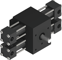
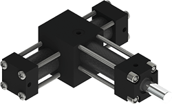
 Multi-Position Multi PositionThree Position ActuatorsA032*80psi
 Torque: 6 in-lb*
Shaft: 1/4" or 3/8"
DiameterA12*80psi Torque: 12 in-lb
Shaft: 3/8"
DiameterA22*80psi Torque: 39 in-lb*
Shaft: 1/2"
DiameterA32*80psi Torque: 119 in-lb*
Shaft: 3/4"
DiameterA42*80psi Torque: 277 in-lb*
Shaft 1 or 1 1/8"
Diameter4 or 5 Position ActuatorsFour or Five Position*80psi Torque: 12-277 in-lb*
Shaft: 3/8"-1 1/8"
Diameter -
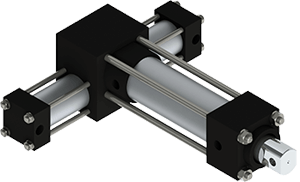
 Indexing Indexing ActuatorsSingle RackX1*60psi
 Torque: 9 in-lb*
Shaft: 3/8*
DiameterX2*60psi Torque: 29 in-lb*
Shaft: 1/2"
DiameterX3*60psi Torque: 89 in-lb*
Shaft: 3/4"
DiameterX4*60psi Torque: 208 in-lb*
Shaft: 1"
Diameter -
 Stepping
 -
 Multi-Motion
 -
 Nitpicker Nitpicker ActuatorsSingle RackPX2*80psi
 Torque: 39 in-lb*
Shaft: 1"
Diameter -
 Shaft Mounting Adapters
Optimizing Your Pneumatic Rotary Actuator with Air Shock Absorbers for High Energy Loads
Pneumatic rotary actuators can impart a very large kinetic energy into an object being rotated. If this energy is not dissipated in a controlled manner, it can lead to damage to the actuator, the part being moved, or the structure of the machine it is part of.
Traditional methods of absorbing this energy include:
- Elastomeric bumpers: these are simple and reliable, but act over a very short range of motion, resulting in very high forces for a given amount of energy. They are primarily used to reduce the noise of a well-controlled stop.
- Pneumatic Cushions: these put an adjustable restriction in the exhausting airflow of the cylinder for the last thirty or so degrees, resulting in a back pressure which can decelerate the load. They can be quite effective but may not have sufficient capacity for very high energy loads.
- Hydraulic Shock Absorbers: Mounted either within the actuator or externally to act directly on the load, hydraulic shocks have progressive porting internally to decelerate the load more efficiently. However, the lifetime of hydraulic shocks is often less than that of the actuator itself, requiring monitoring and periodic replacement. Even a very small loss of internal oil due to leakage can render them inoperable.
For very high energy loads, Rotomation can supply what are essentially air shocks. These are auxiliary cylinders, which are more commonly used to produce four and five position rotary actuators. They are single acting air cylinders whose rod projects into the main cylinders of the actuator a certain distance, so that the actuator piston will make contact with the rod near the end of its stroke. The air shock is pressurized using a separate, relieving regulator and a meter-out flow control. The controllable air pressure and adjustable flow control together offer a broad range of tunability to the system. The stroke of the shock can also be optimized for the application.
The air shocks are made from the same components that are used in the main actuator, so lifetime is similar. They are insensitive to small leaks since the air is constantly replenished. They can even be outfitted with standard pneumatic cushions for an additional stage of cushioning.
With this construction, the shocks can be mounted on both cylinders of a single rack actuator to function in both directions. But in some cases, the speed or load is much greater in one direction than the other, and a single shock can be used. For dual rack actuators, the number of shocks can range from one to four.
If there are shocks supplied for both directions, one will provide a boost of torque for the first portion of the stroke, increasing the rate of acceleration. However, the end-of-stroke shock will reduce the holding torque of the actuator. In most cases, the air pressure supplied to the shock is significantly lower than that of the main actuating cylinders, reducing both effects.
If this effect is too great, a directional control valve can be added to the system to exhaust the shock at the end of stroke, as reported by magnetic switches that are commonly fitted to rotary actuators.
Another way to implement air shocks is by using internal stop tubes added to a dual rack actuator. These stop tubes are normally used to implement a three-position motion. They are plumbed and controlled in the same way as the auxiliary cylinder solution. The advantage of this method is that it has more compact envelope dimensions.
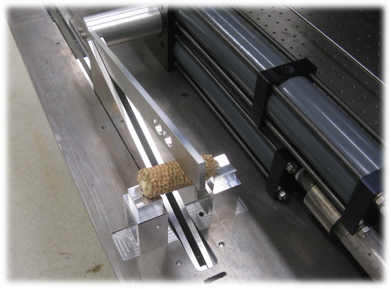
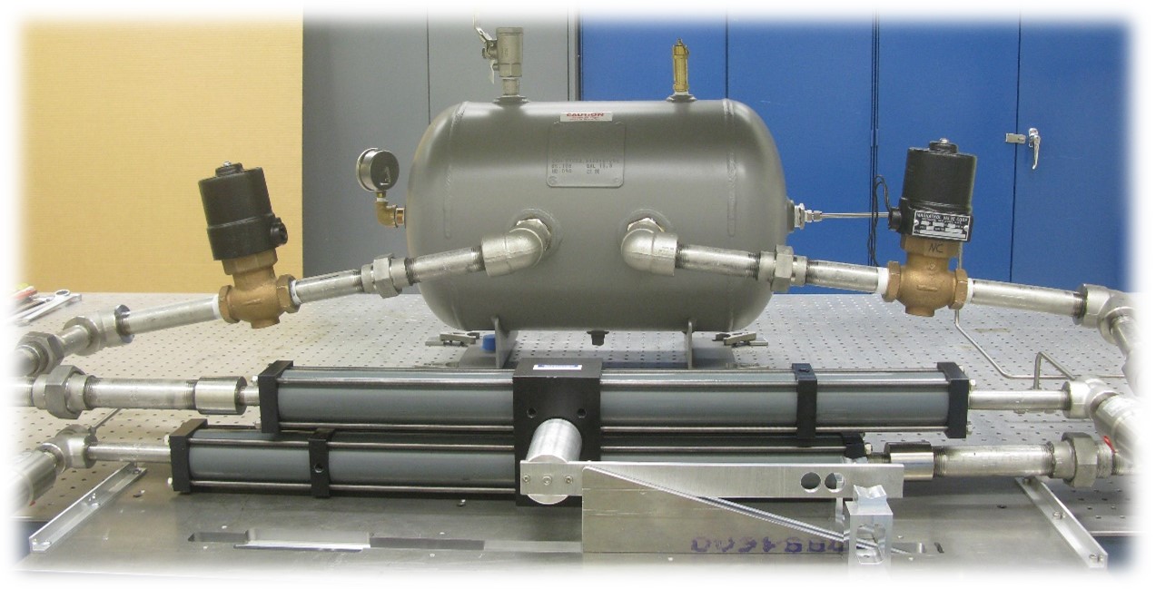
One example of the use of air shocks was when the Idaho National Laboratory was doing research on the energy required to break up agricultural waste materials for use in making biofuels. They wanted to achieve a very high velocity of a blunt blade, so they mounted a long arm onto a Rotomation actuator and outfitted it with a very large capacity air supply including an accumulator to channel a lot of air very quickly. The actuator was equipped with air shocks, oversize ports, and a rear shaft modified to accept an encoder for precise measurement of its position and speed.
In conclusion, with this arrangement, they were able to achieve a velocity greater than their target without damage to the actuator or other components.


