
How Do Rotomation Indexers Work?
Available with washdown option. about Stainless Steel!
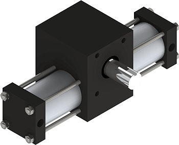
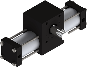
The Rotomation indexer uses the same principle as a standard rotary actuator, where pistons drive a rack back and forth producing a rotary motion of the pinion. But instead of being part of the shaft, the pinion is bored out and has a clutch/bearing pressed in. This clutch/bearing has one set of needles to support the pinion on the shaft, and a separate set of needles that grip the shaft in one direction only.
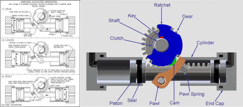
When the pinion is turning in the drive direction, the clutch grabs the shaft and turns it. During the reset stroke, the rack, pinion, and pistons back up, but the shaft stays still because the clutch releases its grip. A second clutch pressed into the body prevents the shaft from turning backward.
A ratchet attached to the shaft provides accurate stops. The ratchet has one tooth for each stop that the indexer will make in one revolution; for example, a ninety degree indexer has a ratchet with four teeth. A pawl rides along on the outside diameter of the ratchet, pushed inward by a spring. The ratchet tooth impacts the pawl, stopping the shaft and load. At this point, the indexer is locked; the pawl prevents forward rotation and the torque produced by the actuator as well as the anti-back up clutch prevents reverse rotation. For positioning applications, the air pressure should be maintained to keep the shaft in this registered location until work on the load is completed. See video featuring our X1 indexing actuator.
Notice that the rack and pinion do not reach the end of their stroke in the drive direction, because the cylinder is made longer. This means that as long as air pressure is maintained on the driving piston, the pinion will continue to push the ratchet against the pawl. It also means that the accuracy is not dependent on the stroke of the actuator; it is completely dependent on the ratchet itself.
Once the work is done, the directional control valve can be shifted to drive the rack and pinion back the other way; this is called the reset stroke. Near the end of the reset stroke, a cam attached to the pinion pushes the pawl away from the ratchet so that it is then free to rotate forward. Once the reset stroke is completed, the next drive stroke can begin immediately. For applications where there is no need to maintain the shaft in a locked position, the reset stroke can be initiated immediately following the completion of the drive stroke, so that the indexer is prepared for a drive stroke immediately following a signal that a part is approaching, for example.
Because of the one-way clutch, the pistons cannot exert a reverse torque on the shaft. This means that the speed of an indexer which has an external force or gravity urging the shaft to rotate in the forward direction cannot be controlled and will likely have damaging impact. For small forces, a constant drag may be added to counteract the force, and has the additional benefit of adding a damping effect which will stabilize the system.
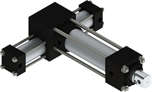
Forward acting torques can also cause problems the reset condition, where the shaft is free to rotate in the clockwise direction. In situations like this, a brake can be utilized to hold the load. All indexing actuators are available with a double ended shaft which can be used as a location for a brake, and if the brake is pneumatic, it can be plumbed in parallel with the indexer so that no extra valves or logic are required.
The free-wheeling behavior in the reset mode can also be used to advantage in some cases, for manual “fast forward” to a loading position, or for clearing jams. Since the ratchet is keyed to the shaft, the indexer will always return to its normal pattern of stops.
Selection
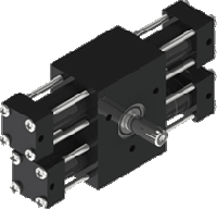
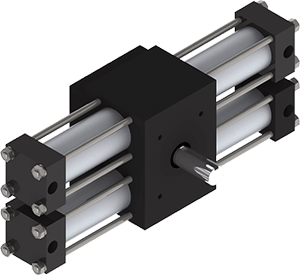
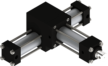
For loads that are primarily inertia, the indexer should be sized by its capacity to stop. The inertia and kinetic energy of the load are the important factors; torque is never the limitation. For this reason, dual rack indexers are seldom a good choice for these loads since they double the torque but do not improve the ability to stop.
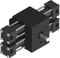
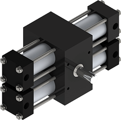
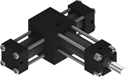
Loads that have high torque relative to inertia are better candidates for dual rack indexers, and include:
- Conveyors with high friction
- Bending or forming applications
- Pushing parts across a surface
- Instances where the load is being lifted against gravity
The Rotomation catalog has guidance, and Rotomation engineers are always available for assistance.
Controls
Cushions on an indexing actuator will have limited effect, because the pistons drive the load through a one-way clutch. Once the load has been accelerated, slowing the rack and pinion using cushions or shock absorbers will simply reduce or eliminate additional torque from being applied. The inertia of the load will carry it unchecked until the ratchet stops it. But if there is sufficient friction to stop the load within approximately thirty degrees, then the cushion will reduce torque for the last thirty degrees and let the friction slow the load for a softer stop.
During the reset stroke, there is nothing occurring that is visible externally. Since there is no load on the rack and pinion, it can shoot back at extremely high velocity if it is not controlled. The only indication to the user is noise and potentially, breakage of gear teeth or other internal parts. A cushion on the reset stroke can be used to minimize the impact, but must be adjusted essentially “by ear”. A bumper on the reset stroke is less effective, but does not need to be set and cannot come out of adjustment.
Speed control using flow control valves is essential to avoid harmful crashes. A moderate to high pressure gets the load up to speed quickly, and the flow control then limits the maximum velocity. Adjusting system pressure to control speed results in constant acceleration, which for a given stroke time, requires a much higher terminal velocity and resulting impact.
Control System Feedback
There are two feedback options available for reporting the indexer’s status to the machine’s control system. Magnetic switches are the same used on standard rotary actuators and report the end of the drive stroke and the end of the reset stroke. If the actuator is advanced manually while in the reset mode, then the pistons will not travel their full stroke on the next drive stroke and may not reach the sensor.
Alternatively, the actuator may be ordered with an extended pawl shaft, which projects out the rear of the body. A user-supplied flag can be attached to this shaft and sensed with proximity detector(s) to provide the same signals. The potential for a missed signal following manual motion is eliminated.
If the system requires absolute position feedback, then external sensors must be used. Rotomation can provide a modified rear shaft and other mounting provision for an encoder or other sensor per special order.
If you have any questions for our engineers regarding our indexing actuators, call us at 386-676-6377 or