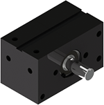
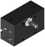
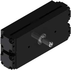
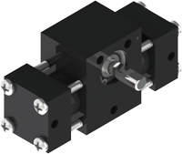
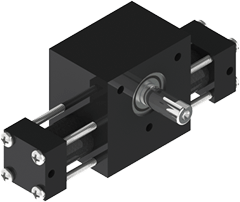
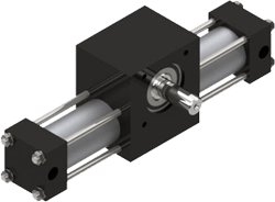
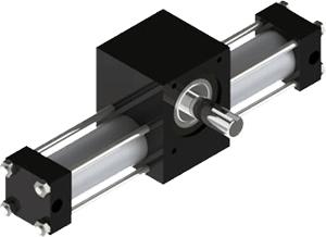
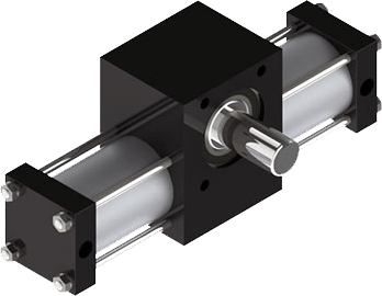
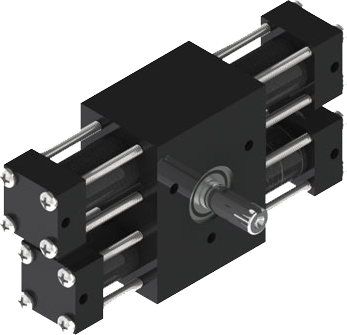
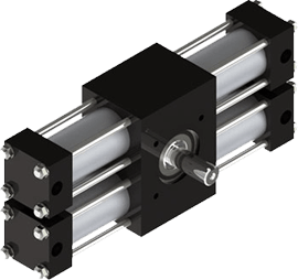
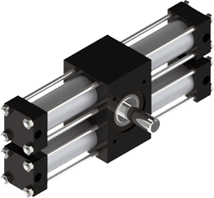
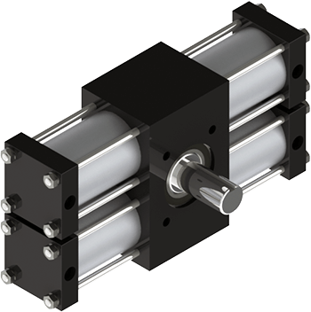
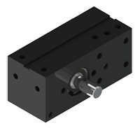

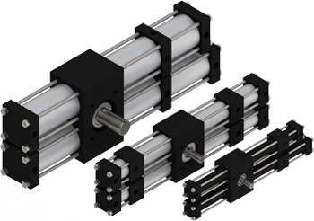
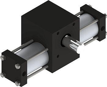
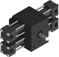
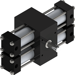
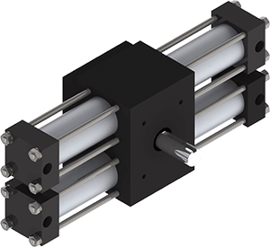
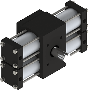
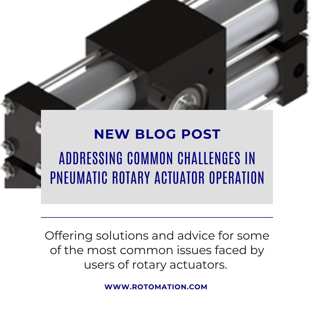
Pneumatic rotary actuators play a pivotal role in the world of automation, bringing a blend of high torque and robust construction packaged in a cost-effective, compact component. External controls are very simple, consisting primarily of a directional control valve, but getting good performance from these actuators requires careful attention to some details.
Controlling Inertia
In numerous applications, the static torque of the actuator isn't the limiting factor; the challenge lies in achieving a smooth, controlled motion with a gentle stop to prevent both noise and potential damage to the actuator and surrounding components. This underscores the importance of sizing the actuator properly with the load's inertia and fine-tuning the operating parameters accordingly.
Essentially, the actuator should be sufficiently sized (displacement) to effectively manage the load's inertia. Since air is compressible, an insufficient displacement in the actuator is like having overly soft springs in a car. The consequence? Sluggish performance and perilous collisions at the end of the rotation.
Flow Controls
Meter-out flow controls play a crucial role in pneumatic actuator applications, enhancing both efficiency and safety. These controls create the buildup of back pressure in the exhausting cylinder, proportional to the square of the load velocity. With an adequately sized actuator, this means that it will accelerate the load quickly and then reach a steady speed. Without the flow control, the load will accelerate continuously, causing a high-speed crash at the end. A properly sized actuator with flow control can move the load in a shorter time with lower terminal velocity.
Cushions
Most pneumatic rotary actuators can be configured with pneumatic cushions to decelerate the load in the final thirty or so degrees of rotation. This minimizes the cycle time for a given amount of shock at the end of stroke. A built-in needle valve acts as a second stage of flow controls, allowing precise adjustment of airflow restriction.
When adjusting, ensure the actuator is in motion, carrying the standard load at the target speed with the standard operating air pressure. If the needle doesn't restrict the airflow sufficiently, the cushion won't have much impact. On the flip side, if it's too restrictive, the cushion pressure builds too quickly, risking a load bounce-back. But hit that sweet spot in adjustment, and the load will decelerate smoothly without unnecessarily extending the cycle time.
For optimal cushion effectiveness, always pair these cushions with meter-out flow controls. Start by adjusting the flow controls first, though be prepared for some back-and-forth fine-tuning. This tag team ensures a seamless, controlled performance.
Bumpers
Bumpers, those resilient pieces of elastomer, typically affixed to the actuator's pistons, play a nifty role in softening the blow – quite literally. As the stroke concludes, these bumpers undergo a gentle compression, siphoning off a chunk of the load's kinetic energy. On their own, bumpers have a modest capacity, but they're a step up from having nothing at all. Excelling at absorbing energy during low-speed maneuvers, they make a perfect match for cushions, which are more effective when dealing with higher speeds.
Hydraulic Shock Absorbers
Some actuator manufacturers offer a solution tailored for high-energy applications: built-in hydraulic shocks. These shocks often outperform pneumatic cushions, thanks to their internal progressive metering. This feature dynamically adjusts fluid restriction throughout the stroke, resulting in a more consistent deceleration force.
However, this approach brings forth several challenges. The shock must be designed to withstand the air pressure within the actuator and efficiently absorb a substantial amount of energy during low-speed, short strokes. Additionally, hydraulic shocks might exhibit a shorter cycle life than the actuator, potentially leading to failure through leakage into the actuator. This leakage can go unnoticed and contaminate both the actuator and the air system, all while leaving the actuator vulnerable to a crash.
To circumvent these issues, a strategic solution involves externally mounting the shocks. Placing them in direct contact with the load at a distance from the center of rotation increases both speed and stroke, creating more favorable conditions for most shocks. This external setup minimizes exposure to the compressed air environment, mitigating potential problems.
Lash
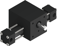
A rack and pinion rotary actuator must have some clearance between the mating teeth of the rack and pinion. This clearance, often referred to as lash, introduces a degree of free play in the shaft. When an external object, like an arm connected to the shaft, is in play, this free movement restricts the precision of its positioning – a factor of significance in certain applications.
The amount of lash can be minimized by the actuator design. Those featuring racks located precisely with respect to the pinion can be made with smaller clearances. While the absolute amount of lash might seem minor, its impact is magnified by the radius of the object undergoing rotation.
There are several solutions to the lash problem:
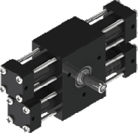
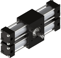
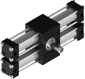
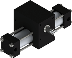
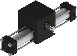
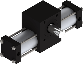
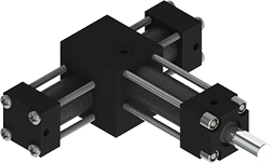
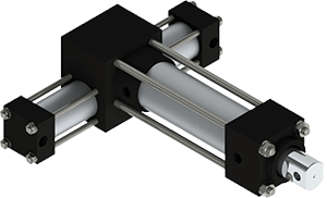
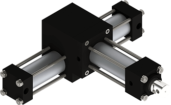
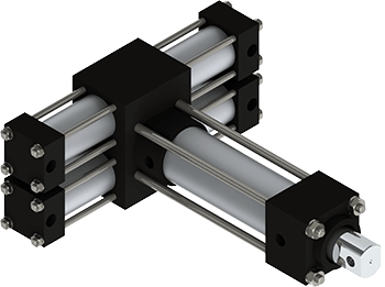
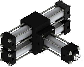
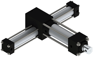
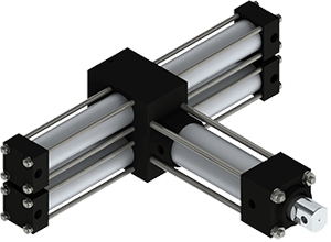
- Dual rack actuators: Most manufacturers of rack and pinion actuators offer dual rack versions. By building some extra stroke into one rack, it will take up the lash at the end of the stroke. Be aware that the resistance to movement in the last fraction of a degree is only the torque of a single rack actuator.
- Vane Actuators: Vane-type actuators offer high torque in a compact package and are naturally lash-free. They are typically less robust and configurable than rack and pinion type but are suitable for many applications.
- External stops: If the actuator is built with more rotation than needed and the load is designed to come up against an external stop, the lash will be eliminated. The stop may have energy-absorbing features such as a bumper or hydraulic shock absorber, shielding the actuator from the shock at the end of the stroke.
Conclusion:
When applied appropriately, pneumatic rotary actuators can offer exceptional functionality in automation.